|
|
Scan angle tables |
||||||||||||||||||||||||||||||||||||||||||||||||||||||||||||||||||||||||||||||||||||||||||||||||||||||||||||||||||||||||||||||||||||||||||||||||||||||||||||||||||||||||||||||||||||||||||||||||||||||||||||||||||||||||||||||||||||||||||||||||||||||||||||||||||||||||||||||||||||||||||||||||||||||||||||||||||||||||||||||||||||||||||||||||||||||||||||||||||||||||||||||||
|
|
|||||||||||||||||||||||||||||||||||||||||||||||||||||||||||||||||||||||||||||||||||||||||||||||||||||||||||||||||||||||||||||||||||||||||||||||||||||||||||||||||||||||||||||||||||||||||||||||||||||||||||||||||||||||||||||||||||||||||||||||||||||||||||||||||||||||||||||||||||||||||||||||||||||||||||||||||||||||||||||||||||||||||||||||||||||||||||||||||||||||||||||||||
|
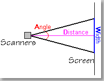
The scan angle and the distance to the screen determine the width of the projected image. |
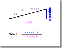
Here's where the scan angle formulas at right come from. In a right triangle, the tangent of the scan angle equals the length of the opposite side divided by the length of the adjacent side. |
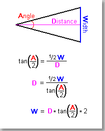
A laser scan is two right triangles, back-to-back. So the right triangle formula is modified to divide or multiply by two at the appropriate point.Caution: Although in the formulas at right you first multiply by two and then divide by two (or vice versa), these operations do not cancel each other out. This is because the tangent is involved and it is non-linear. So don't skip any steps in the calculations. |
![]()
For some applications, it may be necessary to figure out the scan angle, the screen distance or the image width. The formulas and table below will make this easy. To use the formulas, you must know the two of the following three parameters:
• A = Scanning angle in degrees, peak-to-peak. This is also known as the "optical" angle.
• D = Throw distance from the scanners to the screen.
• W = Projected image width (Of course, the image height should also be the same, so both scanners are tuned to the same angle).
The distance and width
must be in the same units, such as feet or meters. The units themselves do
not matter.
There
are two ways to find the unknown (third) parameter. One is by calculations
involving the tangent of A (actually, A
divided by two, since the half-angle must be used). The other is by using
the distance-to-width ratio listing in the table below. Both methods are
described below. Either method gives the same result, so use whichever you
feel is easiest.
The
diagrams at left will help to explain how the calculation formulas were
derived.
To find the scan angle A, knowing the width W and distance D
• By calculation: tan(A/ 2) = W
/ (D * 2).
For example, W
is 109 meters and D is 150 meters. First,
multiply D times 2 to get 300. Then, W
(109) divided by 2*D (300) is 0.3633. Next,
look in the table below, to find the closest angle which has a tangent of
0.3633. This is 20 degrees (at 0.3640). We have just found the half-angle
of scanning; the actual peak-to-peak angle is twice this, or 40 degrees.
Thus, the desired scan angle A is about 40
degrees.
• Using the table: tablewidth@A = (W
* 100) / D.
For example, W
is 109 meters and D is 150 meters. First,
multiply W (109) by 100 to get 10,900. Divide
this by the distance D (150) to get 72.6.
Finally, look down the table at the "Distance-to-width ratio"
column until you find the angle A where the table
width is closest to 72.6. This is at 40 degrees, where the ratio is 100 :
72.8. Thus, the desired scan angle A is about
40 degrees.
To find the distance D, knowing the scan angle A and the width W
• By calculation: D = W/
(tan(A/ 2) * 2).
For example, A
is 40 degrees and W is 109 meters. First,
look in the table below to find the tangent of half of 40, or 20 degrees;
this is 0.3640. Next, multiply 0.3640 times 2. The equation is now W
(109) divided by 0.7280, or 149.7. Thus, the desired distance D
is about 150 meters.
• Using the table: D = (W
/ tablewidth@A) * 100.
For example, A
is 40 degrees and W is 109 meters. First,
look in the table below and find 40 degrees. The distance-to-width ratio
is given as 100 : 72.8. Using the formula, divide W
(109) by 72.8 (the table width at A), to get
1.497. Finally, multiply this by 100 to find 149.7 meters, the desired
distance D.
To find the width W, knowing the scan angle A and the distance D
• By calculation: W= D
* (tan(A / 2) * 2).
For example, A
is 40 degrees and D is 150 meters. First,
look in the table below to find the tangent of half of 40, or 20 degrees;
this is 0.3640. Next, multiply 0.3640 times 2. The equation is now D
(150) times 0.7280, or 109.2. Thus, the desired width W
is about 109 meters.
• Using the table: tablewidth@A *
W = ( D
/ 100 ).
For example, A
is 40 degrees and D is 150 meters. First,
look in the table below and find 40 degrees. The distance-to-width ratio
is given as 100 : 72.8. Therefore the table width at A
is 72.8. Next, divide D
(150) by 100 to get 1.5. Finally, multiply 72.8 by 1.5 to find 109 meters, the desired width W.
Angle data table
| Angle (degrees) | Tangent | Distance-to-width
ratio (if distance is 100 units, width is...) |
Notes |
| 1 | 0.0175 | 100 : 1.7 | |
| 2 | 0.0349 | 100 : 3.5 | |
| 3 | 0.0524 | 100 : 5.2 | |
| 4 | 0.0699 | 100 : 7.0 | |
| 5 | 0.0875 | 100 : 8.7 | |
| 6 | 0.1051 | 100 : 10.5 | |
| 7 | 0.1228 | 100 : 12.2 | |
| 8 | 0.1405 | 100 : 14.0 | ILDA 30K test pattern size |
| 9 | 0.1584 | 100 : 15.7 | |
| 10 | 0.1763 | 100 : 17.5 | |
| 11 | 0.1944 | 100 : 19.3 | |
| 12 | 0.2126 | 100 : 21.0 | |
| 13 | 0.2309 | 100 : 22.8 | |
| 14 | 0.2493 | 100 : 24.6 | Distance is 4 times width |
| 15 | 0.2679 | 100 : 26.3 | |
| 16 | 0.2869 | 100 : 28.1 | |
| 17 | 0.3057 | 100 : 29.9 | |
| 18 | 0.3249 | 100 : 31.6 | |
| 19 | 0.3443 | 100 : 33.5 | Distance is 3 times width |
| 20 | 0.3640 | 100 : 35.3 | |
| 21 | 0.3839 | 100 : 37.1 | |
| 22 | 0.4040 | 100 : 38.9 | |
| 23 | 0.4245 | 100 : 40.7 | |
| 24 | 0.4452 | 100 : 42.5 | |
| 25 | 0.4663 | 100 : 44.3 | |
| 26 | 0.4877 | 100 : 46.2 | |
| 27 | 0.5095 | 100 : 48.0 | |
| 28 | 0.5317 | 100 : 49.9 | Distance is 2 times width |
| 29 | 0.5543 | 100 : 51.7 | |
| 30 | 0.5774 | 100 : 53.6 | |
| 31 | 0.6009 | 100 : 55.5 | |
| 32 | 0.6249 | 100 : 57.3 | |
| 33 | 0.6494 | 100 : 59.2 | |
| 34 | 0.6745 | 100 : 61.1 | |
| 35 | 0.7002 | 100 : 63.1 | |
| 36 | 0.7265 | 100 : 65.0 | |
| 37 | 0.7536 | 100 : 66.9 | |
| 38 | 0.7813 | 100 : 68.9 | |
| 39 | 0.8098 | 100 : 70.8 | |
| 40 | 0.8391 | 100 : 72.8 | This is the nominal limit of G-120 scanners |
| 41 | 0.8693 | 100 : 74.8 | |
| 42 | 0.9004 | 100 : 76.8 | |
| 43 | 0.9325 | 100 : 78.8 | |
| 44 | 0.9657 | 100 : 80.8 | |
| 45 | 1.0000 | 100 : 82.8 | |
| 46 | 1.0355 | 100 : 84.9 | |
| 47 | 1.0724 | 100 : 87.0 | |
| 48 | 1.1106 | 100 : 89.0 | |
| 49 | 1.1504 | 100 : 91.1 | |
| 50 | 1.1918 | 100 : 93.3 | |
| 51 | 1.2349 | 100 : 95.4 | |
| 52 | 1.2799 | 100 : 97.5 | |
| 53 | 1.3270 | 100 : 99.7 | 1:1 ratio -- distance equals width |
| 54 | 1.3764 | 100 : 101.9 | |
| 55 | 1.4281 | 100 : 104.1 | |
| 56 | 1.4826 | 100 : 106.3 | |
| 57 | 1.5299 | 100 : 108.6 | |
| 58 | 1.6003 | 100 : 110.9 | |
| 59 | 1.6643 | 100 : 113.2 | |
| 60 | 1.7321 | 100 : 115.5 | Normal limit of CTI 6800/6210 scanners |
| 61 | 1.8040 | 100 : 117.9 | |
| 62 | 1.8807 | 100 : 120.2 | |
| 63 | 1.9626 | 100 : 122.6 | |
| 64 | 2.0503 | 100 : 125.0 | |
| 65 | 2.1445 | 100 : 127.4 | |
| 66 | 2.2460 | 100 : 129.9 | |
| 67 | 2.3559 | 100 : 132.4 | |
| 68 | 2.4751 | 100 : 134.9 | |
| 69 | 2.6051 | 100 : 137.5 | |
| 70 | 2.7475 | 100 : 140.0 | |
| 71 | 2.9042 | 100 : 142.7 | |
| 72 | 3.0777 | 100 : 145.3 | |
| 73 | 3.2799 | 100 : 148.0 | |
| 74 | 3.4874 | 100 : 150.7 | |
| 75 | 3.7321 | 100 : 153.5 | |
| 76 | 4.0108 | 100 : 156.3 | |
| 77 | 4.3315 | 100 : 159.1 | |
| 78 | 4.7046 | 100 : 162.0 | |
| 79 | 5.1446 | 100 : 164.9 | |
| 80 | 5.6713 | 100 : 167.8 | Absolute limit of CTI 6800/6210 scanners... |
| 81 | 6.3138 | 100 : 170.8 | ...remaining entries are for completeness |
| 82 | 7.1154 | 100 : 173.9 | |
| 83 | 8.1443 | 100 : 176.9 | |
| 84 | 9.5144 | 100 : 180.1 | |
| 85 | 11.430 | 100 : 183.3 | |
| 86 | 14.300 | 100 : 186.5 | |
| 87 | 19.081 | 100 : 189.8 | |
| 88 | 28.636 | 100 : 193.1 | |
| 89 | 57.290 | 100 : 196.5 | |
| 90 | --- | 100 : 200.0 |


